- Install Jesse 2015-11-21
- Go thru the configuration
(Menu > Preferences > Raspberry Pi Configuration) - Under the System Tab:
- Expand the filesystem
- Change the pi password
- Change the Pi Hostname
- Don’t automatically login to ‘pi’ user
- Under the Interfaces Tab:
- Camera = Disable
- SSH = Enable
- SPI = Enable
- I2C = Enable
- Serial = Disable
- I don’t change anything under the Performance Tab
- Under the Localisation Tab:
- Change the locale to Canada (English)
- Set the Timezone to Canada (America) > Mountain (Edmonton)
- I’m still having a problem with changing the keyboard layout
- It is a noted problem on the Raspberry Pi Forum
- Still using sudo raspi-config to config to Canada > English
- sudo apt-get update
- sudo apt-get upgrade
- sudo adduser robin
- sudo visudo to give robin the same rights as pi user
- sudo apt-get install arduino-mk
- sudo apt-get install arduino (add robin to dialout group)
- Make a link to the Arduino.mk file:
ln -s /usr/share/arduino/Arduino.mk ~/Arduino.mk - Copy the original avrdude.conf file into my home directory
- cp /etc/avrdude.conf ~/avrdude_gpio.conf
- Modify it to work with the GPIO pins
- nano ~/avrdude_gpio.conf
- Aff the following lines at the end of the file:
- # Linux GPIO configuration for avrdude
- # Change the lines below to the GPIO pins connected to the AVR
- programmer
- id = "pi_1";
- desc = "Use the Linux sysfs interface to bitbang GPIO lines";
- type = "linuxgpio";
- reset = 12;
- sck = 24;
- mosi = 23;
- miso = 18;
- ;
- With the Arduino connected to the Raspberry Pi, run the following line to make sure the Raspi can see the arduino:
sudo avrdude -p atmega328p -C ~/avrdude_gpio.conf -c pi_1 -v - git clone https://github.com/robingreig/raspi-git
- cp -r ~/raspi-git/Python ~ (to copy the Python directory to my home)
- cp -r ~/raspi-git/Uno ~ (to copy the Uno directory to my home)
- Goto the .hex file @ ~/Uno/Serial/Voltages/build-uno/Voltages.hex & run:
sudo avrdude -p atmega328p -C ~/avrdude_gpio.conf -c pi_1 -v -U flash:w:Voltages.hex:i - If you overwrite the bootloader, reload it by going to:
cd /usr/share/arduino/hardware/arduino/bootloaders/optiboot/
and running the avrdude line with the optiboot_atmega328.hex file
Wednesday, December 16, 2015
Avrdude 6.1
I just installed the latest version of Raspbian Jessie 2015-11-21 for my Pi 2's. I found that now when I installed the arduino package, it comes with avrdude 6.1. So I don't need to link to the adafruit repository anymore. Here is a list of the steps I take to install Jessie, Arduino, Arduino-mk, and check that I can communicate between the Arduino & Raspberry Pi 2 via Serial. You'll note that I clone my git repository where I keep all of my files as I'm working on them. I find this extremely useful since I'm working on the files on my Pi2 or Gertduino/PiB at home, or the same setup that I have at work:
Wednesday, December 9, 2015
Raspberry Pi takes over the world

OK, if not the world, then 1 outlet at a time!!!
This is a pic of a single relay that is controlled by my Raspberry Pi.
Red = 5VDC, Black = Ground, White = Pin23 (active high)
And an old pc power cord split in 1/2 and a female end installed.
The Ground and Neutral leads feed straight through from the input to the output
The relay switches the hot lead and runs a battery charger drawing 5 Amps AC.
The relay is rated for 10A @ 277V
The Raspberry Pi runs off of my solar array at home and because I have so many items tied to them:
3 Raspberry Pi's
1 x 12V HP switch
1 x Kenwood HF Amateur Radio
1 x LDG Antenna Tuner
1 x Radio Shack HTX-242 VHF Amateur Radio
Most days I have enough solar energy to power all my devices.
However if I get several cloudy days together, the voltage can drop and my charge controllers shut down.
Then my Raspberry Pi's shut down...... And that makes me cranky.....
So I have an Arduino monitoring the battery voltage and sends that data via serial to the Raspi
If the battery voltage drops down too much due to lack of sunlight, the charger is turned on for a charge cycle (typically 6-8 hours), and then shuts off.
I plan on making quite a few of these for the many different 120VAC loads that I want to control from my Raspi.
Thanks for viewing;
Robin
Monday, December 7, 2015
Upgrade from Halogen to LED

So, what do you do when you want to change from the small halogen lamps to LED?
Problem is that many halogen power supplies are rated @ 12 VAC, and LED's require 12 VDC.
What I've done here is to add a bridge rectifier and 1000uF/35V Capacitor to a small adjustable power supply.
Packed it in a small Hammond case and works like a charm!!!
I can feed this from the halogen supply with AC, and adjust it to deliver clean 12VDC to my LED's
I've got a customer with quite a few of these lites in all of their bathrooms, etc and it is very difficult to get at the halogen power supply.
So I can simply add this inline at the beginning of the lamp string(s), and presto! even more energy efficient lighting!!!
Thanks for viewing,
Robin
Friday, December 4, 2015
Raspberry Pi & Arduino talking nicely!!!

This is a picture of success!!!
Once again many thanks have to go out to Tony DiCola of Adafruit for publishing his most AWESOME tutorial on Programming an Arduino using the Raspberry Pi GPIO
This enabled me to upgrade to Avrdude 6.1 from the Adafruit Repository and then program the Arduino thru the ICSP header from the GPIO pins.
.... And the bonus is that I can leave my serial connection from the Raspi to the Arduino connected while the programming is taking place!!!!!
So follow his steps to download the new version of Avrdude to your Raspi and hook up the pins from the GPIO header to the Arduino ICSP header.
Test run the program to ensure it can see the Arduino and you're off!
You need to directly upload a .hex file using Avrdude, so the Arduino IDE will do the converting/building for you from .ino to .hex.
I've been using Arduino-mk to upload my .ino sketches (since I like using the command line), so now I just use Arduino-mk to make the sketches, and Avrudude61 to upload them.
The following steps outline Tony's process:
Step 1 - Add the Adafruit repository to the Raspi list using the command:
curl -sLS https://apt.adafruit.com/add | sudo bash
Step 2 - Install the new version of Avrdude by running the following:
sudo apt-get install avrdude
Step 3 - copy the /etc/avrdude.conf file to my home directory and rename it ~/avrdude_gpio.conf
Step 4 - add the following test to the end of the .conf file in my directory:
# Linux GPIO configuration for avrdude
# Change the lines below to the GPIO pins connected to the AVR.
programmer
id = "pi_1";
desc = "Use the Linux sysfs interface to bitbang GPIO lines";
type = "linuxgpio";
reset = 12;
sck = 24;
mosi = 23;
miso = 18;
;
Step 5 - run the following command to confirm connection to the Arduino:
sudo avrdude -p atmega328p -C ~/avrdude_gpio.conf -c pi_1 -v
Step 6 - Once successful, goto a directory with the .hex file you want to upload to the Arduino and run the following command:
sudo avrdude -p atmega328p -C ~/avrdude_gpio.conf -c pi_1 -v -U flash:w:Blink.cpp.hex:i
>>> and you should be able to watch Avrdude upload the sketch and verify it.
++++++++ Oh Yeah, and this is my first post done completely on my Rapsberry Pi 2 in the picture!!!! A little slower than I'm used to, but works great!!! +++++++
Sunday, November 15, 2015
Arduino & Raspberry Pi fighting

This has been my focus over the last couple of weeks (after my day job of course and the other courses I'm teaching!!!)
The top left is of course a Raspberry Pi2
To the right is an Arduino Uno clone
To the right of it is a relay board with 2 x 5VDC relays triggered from the Uno
And just above the relay board is my 12V > 5VDC power supply.
The bottom board and breadboard is a Raspi B model with a Gertduino board plugged in above it (you see 2 blue LED's lit). This is my prototyping setup for the Raspi > Uno Communications.
The Arduino powers on the left hand relay (you can just make out the Red LED) which powers on the Raspberry Pi (Raspi).
As well, the Uno monitors my battery voltage on Analogue A0 pin (batteries are not pictured).
The Raspberry Pi polls the Arduino for the Battery Voltage & if the battery voltage drops to 10.5VDC, the Raspberry Pi goes into shutdown (via a python script).
The Arduino continues to monitor the battery voltage and if it drops down to 10VDC, it shuts off the relay which powers the Raspberry Pi down safely.
Once the power is restored, the Arduino powers up and then powers up the Raspberry Pi safely.
The problem I've been struggling with though, is when the Raspberry Pi polls the Uno via the USB Cable (shown unplugged from the Uno in the picture above) the Uno resets every time which changes it's Digital output pins, which shuts down the Raspi......
Thanks to the great folks on the Arduino Forum (UKHeliBob & Robin2) I learned that when the Raspi talks to the Uno via the USB cable it includes resetting the Uno which resets the Digital pins......
What I needed to do was to talk via the 3 wire Serial (Tx, Rx, GND) between the Raspi & Uno and now no problems!!!!
You can see there is a purple and grey wire, as well as a Green/White pair running from the Uno to the Raspi. The Green/White pair have a set of resistors to drop the Uno 5VDC down to the Raspi 3.3VDC for the Serial comms. the other wires are the ground connections (1 redundant)
So it is a bit more work, to use the USB cable to program and then switch over to the 3 wire serial for comms, but really to see it working properly is not problem at all!!!
Sunday, November 1, 2015
VE6RBN-1 Back Online!!!
Wow!
My didipeater VE6RBN-1 has been offline for sometime and I didn't notice it.....
It was transmitting fine, but not digipeating the packets it received over the air...
Apparently my troubleshooting skills are really, really rusty because I checked out the complete TNC and radio, before looking that the obvious problems like wiring....
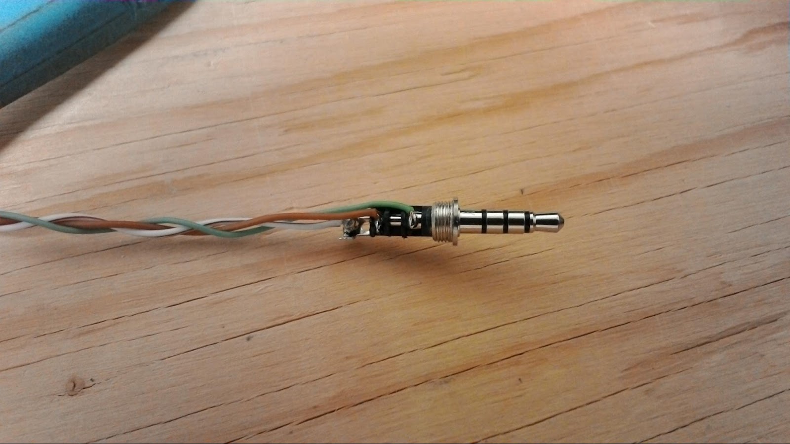
There was a broken connection in the 3.5mm connector that plugs into the Yaesu FT-60 radio and I needed to resolder it.
The brown wire in the picture above sends the received data from the radio to the TNC, and so mine was not able to hear any transmissions.
Yeah, I know that I should use proper wire, not CAT5 solid core, but that's what was on hand to make up the cable.....
Thanks for visiting,
Robin
My didipeater VE6RBN-1 has been offline for sometime and I didn't notice it.....
It was transmitting fine, but not digipeating the packets it received over the air...
Apparently my troubleshooting skills are really, really rusty because I checked out the complete TNC and radio, before looking that the obvious problems like wiring....
There was a broken connection in the 3.5mm connector that plugs into the Yaesu FT-60 radio and I needed to resolder it.
The brown wire in the picture above sends the received data from the radio to the TNC, and so mine was not able to hear any transmissions.
Yeah, I know that I should use proper wire, not CAT5 solid core, but that's what was on hand to make up the cable.....
Thanks for visiting,
Robin
Wednesday, September 16, 2015
Monitoring Vehicle Voltages
Wow!
My last post was in March!
I certainly enjoyed the summer and am looking forward to spending more time back on the bench.
I did stay tinkering during the summer with interconnecting my Raspberry Pi's with Arduino Nano's and Uno's.
The pic below shows my Raspberry Pi connected via USB to my Arduino Uno. I use the analog inputs on the Arduino to monitor the battery voltages in a couple of vehicles that I don't drive every day and to copy that up to a webpage

The small circuit board in the upper right corner is a DC - DC converter and I use it to convert 12VDC down to 5VDC for the Pi and Arduino. It is rated for 5A, so I should have lots of capacity. I've started using Anderson Powerpoles for all of my 12V circuits in my garage and ham shack for interoperability.
Having the power supply on the board also allows me to use a homebrewed POE cable so that I can power and communicate with the Raspberry Pi with one ethernet cable. 4 wires are used for communication and 4 for power (2 + & 2-),

I've also wanted to move away from the Arduino IDE because I usually spend my time ssh'ing into my devices. So I've come across an awesome program arduino-mk which allows you to edit the .ino files with your favorite editor and then use their Makefile to upload it to the arduino. I've successfully used this with the GertDuino, Arduino Nano, and Arduino Uno.
Thanks for visiting;
Robin
Saturday, March 7, 2015
Update on posting to aprs.fi
Things have been quite hectic around here for the last few weeks so I haven't had a chance to post. I been asked to add some additional detail to the process I use to send my house / outdoor / & garage temperatures to aprs.fi.
I've updated my git repository (www.github.com/robingreig/raspi-git/aprx) with the latest files.
***** aprx.conf is now my configuration file with all of the custom beacon files included *****
beacon01.txt is the actual beacon file that transmits the temperatures & is beaconed every 10 minutes
T#136,22.5,38.7,15.7,0,0,00000000
T# = Telemetry
136 is my unique number (0 to a maximum of 999) each day.
***I take temperature readings every 10 minutes and save them to the file, then I take the # of minutes since midnight for this beacon file / 4 to give me a unique number and copy that to this text file
So the unique number for my first beacon file should be 10 minutes past midnight / 4 = 2
Second unique number for the second beacon file = 20 minutes / 4 = 5
Since there are 1440 minutes in a day (24 hours x 60 minutes) / 4 my maximum beacon number would be 360 each day before it resets.
22.5 = House Temperature
37.7 = Outside Temperature + 40
*** Remembering that the number sent has to be between 0 & 255, if it is cold and I have a negative temperature, it won't send properly. So, worst case my outside temp would be -40C, so I add 40 to the outside temp so even worst case, my number would be 0. Then within my equations text file, I subtract 40 off the number to return to the actual outside temperature.
15.7 = Garage Temperatur
0,0,00000000 are additional values that are not used, but in my experience I needed to add them to the string for it to be recognized properly.
beacon02.txt is the parameters file and is beaconed every 120 minutes
:VE6RBN-1 :PARM.House Temp,Outside Temp,Garage Temp
This is a static text file that is beaconed, it does not change, since my parameters don't change
beacon03.txt is the units of measure file and is beaconed every 120 minutes
:VE6RBN-1 :UNIT.Deg C,Deg C,Deg C
This is a static text file as well and doesn't change.
beacon04.txt is the equations file and is beaconed every 120 minutes
:VE6RBN-1 :EQNS.0,1,0,0,1,-40,0,1,0
There are 3 variables sent for every parameter
House Temp (first set of 3) = 0, 1 , 0
Outside Temp (second set of 3) = 0, 1, -40
Garage Temp (third set of 3) = 0, 1, 0
First number of the set is used if we want to square the variable ( which I don't need to do)
Second number is a multiplier (I don't want to multiply my value, so I set it to 1, value x 1 = value)
Third number is a value to add to your variable.
Remembering that I added 40 to my outside temperature, here I subtract 40 from my outside variable to bring the value back to where it should be.
The only other point I wanted to bring up was that I haven't had time to experiment with sending these values out over the air, so I've set my 3 static beacon files (beacon02, beacon03, & beacon04) to be sent out over the internet only. As time allows I want to play with sending this information out over the air in a way that will be displayed properly.
Thanks for reading,
Robin
Sunday, February 8, 2015
Posting Temperature on APRS.fi
I've been working on understanding how telemetry data is sent via APRS. I found a good link on the APRS Site.
It showed me the format of the Telemetry String: T#sss,111,222,333,444,555,xxxxxxxx.
T# defines the string as a telemetry string.
They referred to the first set of numbers (sss) as the serial number and I found that it had to be a unique number from 1 - 999, each day.
I take that to mean that one could only send 999 telemetry packets over the course of the day.
The following 5 groups (111,222,333,444,555) are 5 different 3 digit, analogue values that need to be between 0 - 255.
And the final 8 are binary values which could show (open doors, devices on/off, etc)
So the first challenge I had was to determine how to setup a unique 3 digit number for each transmission, that would reset each day. I decided to go with time.
There are 24 hours x 60 minutes = 1440 minutes in a day, so that is more than 999 & won't quite work.
But I could take the total minutes of the day and divide it by 4.
Here is the Python code that I'm using:
I use the "if DEBUG > 0:" statements to print out values to help me debug a problem. Once it is working properly, I set DEBUG to 0 so they won't print during the execution of the program.
aprs_hour = int(time.strftime("%H"))
if DEBUG > 0:
print "aprs_hour: ", aprs_hour
aprs_minute = int(time.strftime("%M"))
if DEBUG > 0:
print "aprs_minute: ", aprs_minute
aprs_time = int((aprs_hour * 60) + (aprs_minute))
The second challenge that I encountered was the outside temp.
Initially I expected to send the raw value with no problem.
February in Calgary doesn't generate positive values (grin) and so I was stuck for a bit when I saw the correct numbers being sent (-13.6 to -15.0 deg C on the day of my test) but the graph didn't move off of 0.
Then I remembered the values needed to be between 0 - 255.
Assuming the coldest temp of -40C I simply added 40 to the existing temp to bring it to a positive value and then had to figure out how to bring it back to the actual values in aprs.
After further research, I found out about the EQNS aprs string.
Each analogue value is placed into a quadratic equation and one can send the values to modify it.
There are 3 numbers sent for each analogue value as follows:
Each analogue value is placed into a quadratic equation and one can send the values to modify it.
There are 3 numbers sent for each analogue value as follows:
EQNS.abc,def,ghi,jkl,mno
Since analogue value #2 is for my outside temperature, there are 3 values d, e, f that will be placed in the following equation: (Value of #2 x d2) + (Value of #2 x e) + f
So in my case of the negative outside temp, I converted it to a positive by adding 40 to it before it was sent.
My numbers for Value #2 were 0,1,-40. 0 because I didn't want to square it, 1 because I wanted the value and -40 because I had added 40 to the original value, and now needed to subtract it.
My numbers for Value #2 were 0,1,-40. 0 because I didn't want to square it, 1 because I wanted the value and -40 because I had added 40 to the original value, and now needed to subtract it.
I've setup aprx to send out these 3 fields every 120 mins:
:VE6RBN-1 :EQNS.0,1,0,0,1,-40,0,1,0
:VE6RBN-1 :UNIT.Deg C,Deg C,Deg C
:VE6RBN-1 :PARM.House Temp,Outside Temp,Garage Temp
And I've setup the temperature beacon file to be sent out every 10 minutes.
T#199,23.3,31.2,15.5,0,0,00000000
The unique number (199 above) resets at midnight every day.
You can see the telemetry graphed here: VE6RBN-1 Telemetry
And you can see the raw packets here: VE6RBN-1 Raw Packets
And I've setup the temperature beacon file to be sent out every 10 minutes.
T#199,23.3,31.2,15.5,0,0,00000000
The unique number (199 above) resets at midnight every day.
You can see the telemetry graphed here: VE6RBN-1 Telemetry
And you can see the raw packets here: VE6RBN-1 Raw Packets
Friday, January 30, 2015
Burnt Arduino
So what happens when you have a zener diode short out and rather than feed 5VDC to the Arduino Analogue Input, we feed 15VDC?
Yes, you guessed it! We let the magic smoke out!!!
If you look at the left side of the Arduino chip, you'll see a small bump, That bump is the melted plastic from the chip burning up!

Yes, you guessed it! We let the magic smoke out!!!
If you look at the left side of the Arduino chip, you'll see a small bump, That bump is the melted plastic from the chip burning up!

Sunday, January 25, 2015
Raspi & Gertduino UPS
I have purchased a couple of Arduino boards that are made specifically for the Raspberry Pi and they are named after their inventor Gert van Loo, Gertduino. The specs, software, and manual are available via this link.

It is a great platform to work on the inter-communication between the Raspi and the Arduino. I'll be using this combination to further develop my battery monitoring system for my Raspi UPS.
The Arduino will have a 3 level response:
1) My plan is to have my Raspi backup battery charged via the solar panels.
2) The Arduino will monitor the battery voltage. If there is very little sun, or too much load, then the arduino can switch on the 110VAC battery charger to charge the batteries back up.
3) The Arduino will continue to monitor the battery voltage, and if there is no sun AND no utility power, then the Arduino will safely shut down the Raspi if the voltage drops to a preset level. If the voltage continues to drop, the arduino will shut off as well.
NOTE: The advantage of the Arduino is that it can safely recover from a power outage, where the Raspi may not. So the Arduino will power back up and when the battery voltage reaches a preset level, it will power up the Raspi.
ARDUINO vs GERTDUINO: I like working with the Gertduino since it is mounted on the Raspi that it communicates with. However, I've been able to communicate with a regular Arduino Nano as well, so this would be the device I will use as my Battery Monitor, freeing the Raspi GPIO pins for other uses.
Wednesday, January 21, 2015
Raspi & APRX
For some reason when I completed the assembly of my RaspiTNC, I couldn't get it to run with APRX software, yet I was able to get it running on XASTIR. So I knew that my transmit and receive was working fine.... and had assumed (correctly) that I had probably made a mistake in my configuration file. I've gone back now and revisited the APRX Software page and re-read the APRX Manual. This time around I still had issues, but with the help of the APRX-Software Google Group I was able to find my configuration problem (I had left the - in my APRSIS password, so it wouldn't connect). Also I have to say that using my portable APRS setup = ASUS tablet running APRSDroid & Yaesu VX-6R & Mobilinkd TNC makes it easy to test out my iGate configurations.


Subscribe to:
Posts (Atom)